
The TMR0 module is an 8-bit timer/counter with the following features: $$RegValue = TimerMax-((Delay * Fosc)/(Prescalar*4))$$īelow table provides the formula for all the three Timers.

RegValue = TimerMax-(Delay/tick) = TimerMax - (Delay/((Prescalar *4)/Fosc)) Now the Timer value for the required delay can be calculated as below. Time to increment the Timer count by one(timer tick) can be determined as below. PIC Oscillator frequency is divided by 4 and then fed to the controller, Now this this freq can be further divided by presacalar to generate the range of delays. Pic16f877a has three indepenndent timer which can be used as timer,Counters or for PWM generation.īelow table provides the details of the three Timers. Once it reaches the Max value, it will roll back to zero setting up an OverFlow flag and generates the interrupt if enabled. Timer is nothing but a simple binary counter that can be configured to count clock pulses(Internal/External). The microcontroller can also generate/measure the required time delays by running loops, but the timer/counter relieves the CPU from that redundant and repetitive task, allowing it to allocate maximum processing time for other tasks. If (dt > 0.As the name suggests these are used to measure the time or generate the accurate time delay.

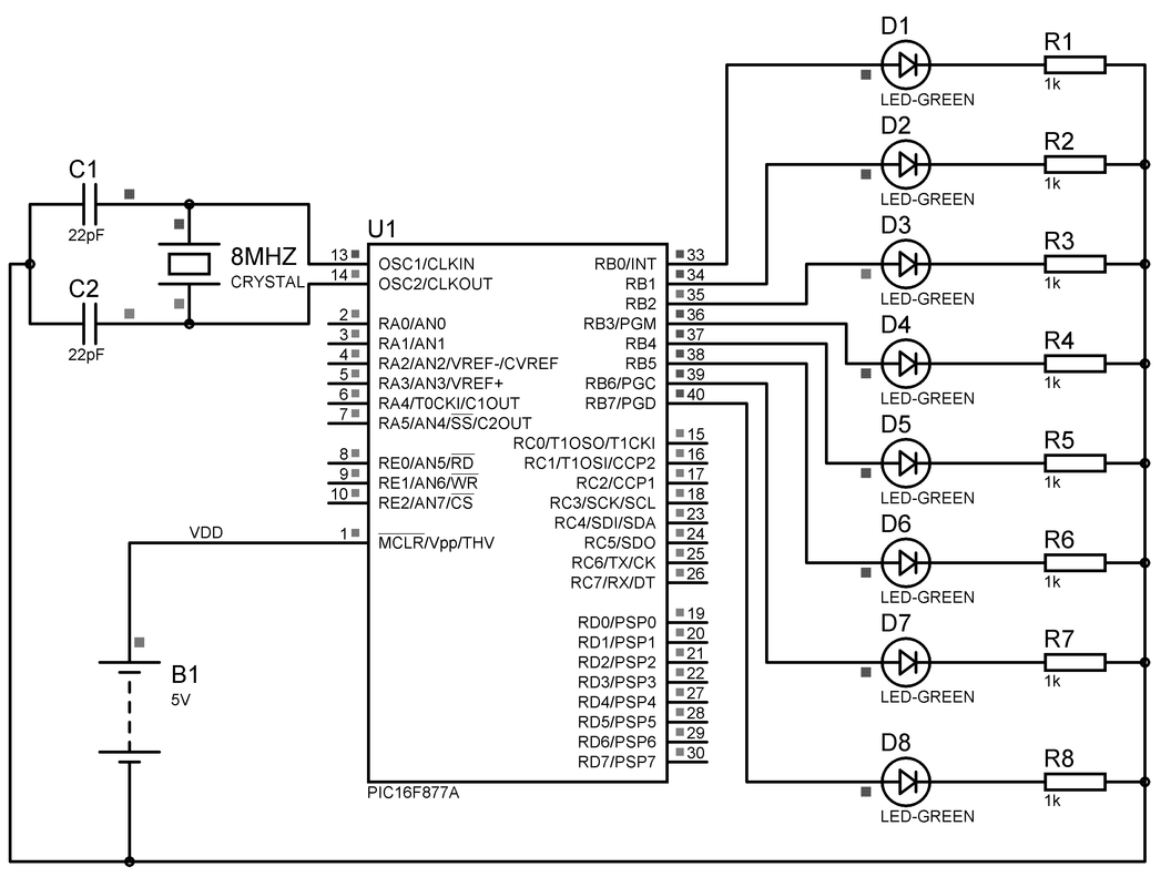
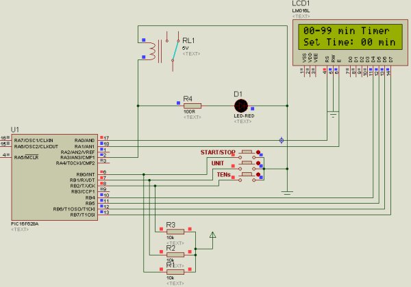
Derivative part = (process value - last process value) / dt Pid->cv_max = 255.0 // Maximum Control Value Pid->cv_min = 5.0 // Minimum Control Value I´v done a float based PID some time ago. uk=(uk_1+(kp+ki*T)*error-kp*ek_1) // Velocity formĪnd this is a file that represents the circuit diagram Uk=kp*error+ki*(error+ek_1)*T // Positional form of a PI // First order system parameters and calculation of PI parametersĮrror=(float)((desired-measured)*5000/1024) The step response of the system was not as that theoritcally expectedįloat error,kp,ki,ek_1,uk,uk_1,T,ta,k,ts,a,b I have written a program in mikroC that performs the task (PID control algorithm), but the result was not correct.


 0 kommentar(er)
